
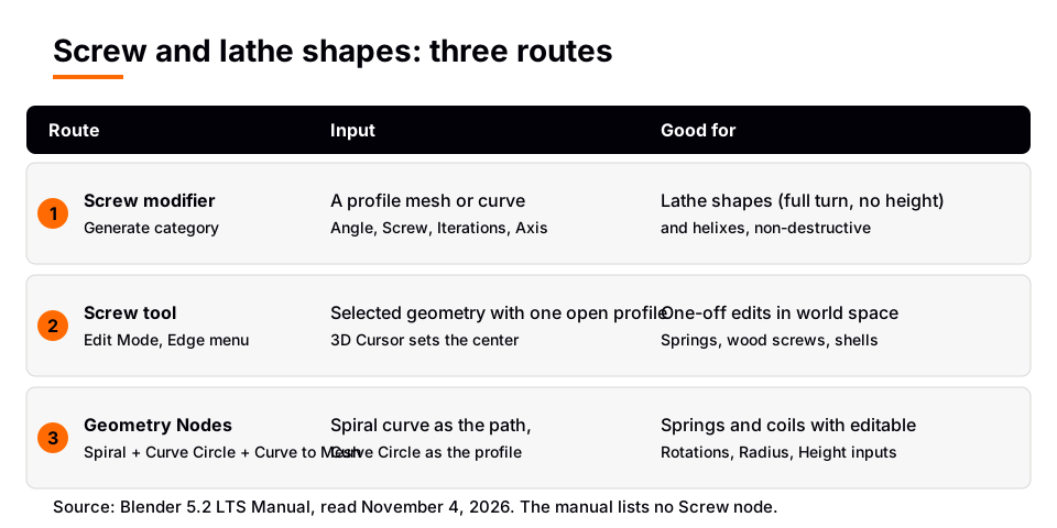
Blender 5.2 has a Screw modifier, but the manual's Geometry Nodes node list has no Screw node. For a lathe or helix, use the Screw modifier on a profile; for a node-based coil, feed a Spiral node into Curve to Mesh with a Curve Circle as the profile. So the "Geometry Nodes Screw modifier" you may be searching for is really two separate tools, and this guide shows how to use each and how to combine them.
Everything below comes from the Blender 5.2 LTS manual. Where the manual does not document a recipe, we say so instead of guessing.
Is there a Screw node in Geometry Nodes?
No node named Screw, Spin or Revolve appears in the 5.2 manual's Geometry Nodes node list. We searched the list for those names, and for lathe, and found only the Spiral node, which generates a curve. The Screw modifier lives in the Generate category of ordinary modifiers.
That does not stop you combining them. The manual's Geometry Nodes modifier page and introduction say the geometry from before the modifier, including the result of the previous modifier, goes into the Group Input node. So you can put a Screw modifier first, then a Geometry Nodes modifier below it that scatters, deforms or otherwise builds on the screwed mesh.
Sources: Geometry Nodes node list · Geometry Nodes modifier page
How the Screw modifier works
The Screw modifier takes a profile object, a mesh or a curve, and creates a helix-like shape from it. Add it from the Modifiers tab of the Properties editor (Add Modifier, or Shift+A in that tab), under Generate. The manual stresses that the profile must be aligned with the cardinal direction of the object, not with the screw axis.
| Option | What the manual says | Effect |
|---|---|---|
| Angle | Degrees for a single helix revolution | How far one turn goes |
| Screw | The height of one helix iteration | Rise per turn |
| Iterations | Number of revolutions | How many turns |
| Axis | The axis along which the helix will be built | Which way the shape is built |
| Steps (Viewport, Render) | Steps for one revolution, shown in the viewport or used at render | Smoothness |
| Merge, Merge Distance | Merge vertices that lie on the axis, closing endpoints with a triangle fan | Closed tips |
There are also Axis Object and Object Screw options, which use another object to define the axis direction and the height of one iteration. Under Normals, Smooth Shading outputs smooth faces, Calculate Order avoids problems with normals and shading on meshes, and Flip reverses the normals. Stretch UVs stretches UV coordinates from 0.0 to 1.0 when UVs are present.
Sources: Screw modifier
Make a lathe (vase) with the Screw modifier
- Make a profile. Model a flat outline of the shape you want, such as half a vase, as a row of connected vertices on one side of the object's origin. A curve profile also works, since the manual allows a mesh or a curve.
- Add the modifier. Add the Screw modifier and choose the Axis that the profile should turn around.
- Set one full turn with no rise. Set Angle to 360 and Iterations to 1, and set Screw to 0. By the manual's definitions, Screw is the height of one iteration, so a value of zero should add no height per turn and the profile sweeps a ring instead of a helix.
- Raise the steps. Increase Steps for Viewport and Render until the round shape looks smooth.
- Close the ends. If the profile touches the axis of rotation, turn on Merge so those vertices join, which the manual says can close endpoints with a triangle fan.
- Fix shading. Turn on Smooth Shading for the output, and use Flip if the normals point inward.
If the result looks twisted or sits off center, the first thing to check is the profile alignment, because the manual says that is the important part. Move the profile or change the object's origin until it lines up with the axis you chose.
Make a helix or screw thread
For a spring-like or threaded shape with the same modifier, keep the profile and give Screw a height. A larger Screw value raises the shape by that distance every turn, and Iterations decides how many turns. Set Angle to 360 for full turns. The manual also describes the Screw tool in Edit Mode (Edge > Screw) for quick one-off helixes, with differences from the modifier:
| Edit Mode Screw tool | Screw modifier | Why it matters |
|---|---|---|
| Works in world space | Works in object space | Tool depends on view and cursor |
| Extrudes only selected geometry | Extrudes all geometry | Modifier uses the whole object |
| Center is the 3D Cursor | Center is the object origin | Move the cursor or the origin |
| One revolution is always 360 degrees | Angle can be chosen freely | Modifier suits partial turns |
| Height set from the geometry | Height set manually | Tool needs an open profile |
Build a spring in Geometry Nodes with Spiral and Curve to Mesh
When you want a coil you can adjust with sliders, build it from three nodes. This is the closest node-based equivalent to a Screw modifier helix that the manual documents.
- Add the modifier. Select a mesh object, add a Geometry Nodes modifier, and open the Geometry Node editor with a node group on the modifier. The Group Input and Group Output nodes are your start and end points.
- Add a Spiral node. The Spiral node generates a poly spline in a spiral shape and the manual says it can be used to create springs. Its inputs are Resolution (points in one rotation), Rotations, Start Radius, End Radius, Height and Reverse. Radius changes linearly between the start and end values, and the spiral twists clockwise unless Reverse is on.
- Add a Curve Circle node. The Curve Circle node generates a poly spline circle with Resolution and Radius inputs. This is the wire cross-section.
- Add a Curve to Mesh node. The Curve to Mesh node converts all splines of a curve to a mesh. Connect the Spiral's Curve output to Curve to Mesh's Curve input and the Curve Circle's Curve output to its Profile Curve input. With a profile, it is extruded along the spline; without one, you only get a chain of edges.
- Close the ends. Turn on Fill Caps if you want n-gon caps on a cyclic profile.
- Send it out. Connect Curve to Mesh's Mesh output to Group Output.
You should see a coiled tube. Change Rotations and Height on the Spiral for the number of turns and the total height, Radius on the Curve Circle for the wire thickness, and raise Resolution on both for a smoother result. The pitch of each turn is the Height divided by the Rotations, which is our arithmetic from those two definitions rather than a manual statement.
The node route works differently from the Screw modifier: the path is a curve and the profile is a circle, rather than a mesh outline spun around an axis. For lathe shapes, we found no node-only recipe in the manual, so use the Screw modifier above.
Sources: Spiral node · Curve Circle node · Curve to Mesh node
Combine the Screw modifier and Geometry Nodes
Here is a stack that uses both, relying only on the stacking behavior in the manual:
- Screw modifier at the top, building the lathe or helix from your profile.
- Geometry Nodes modifier below it, receiving the screwed mesh as its Group Input geometry.
- Nodes of your choice, such as Distribute Points on Faces and Instance on Points to scatter details over the surface. See our Blender Geometry Nodes beginner guide for that setup.
New modifiers go at the bottom of the stack, and the stack is evaluated top to bottom, so check the order if a result looks wrong. For clean edges on the result, read how to bevel in Blender. For wider modeling workflows, see hard surface modeling in Blender.
Learn Geometry Nodes in order with The Blender Launchpad
Screws, springs and lathes are good practice for both modifiers and nodes, but they sit on top of modeling basics and a clear mental model of Geometry Nodes. The Blender Launchpad is a members app with a roadmap of hand picked, free YouTube lessons in six stages. Stage 2 is hard surface modeling, and stage 6 is Geometry Nodes with a Geometry Nodes Launchpad of eight modules included.
Stage 1 assumes you have never opened Blender. The Launchpad is a curated playbook, not original video lessons. It is one payment with no subscription. For a gentler start on modeling, read the Blender 3D modeling tutorial.
Questions people also ask
Is there a Screw modifier node in Blender Geometry Nodes?
No. The Geometry Nodes node list in the Blender 5.2 manual has no Screw node. The Screw modifier is a separate modifier in the Generate category.
How do I make a spring or spiral in Geometry Nodes?
Use a Spiral node for the path, a Curve Circle node for the profile, and a Curve to Mesh node to join them. The manual says the Spiral node can be used to create springs.
How do I make a lathe or vase in Blender?
Model a profile, add a Screw modifier, set Angle to 360, Iterations to 1 and Screw to 0, then raise the Steps. The manual does not document a node-only lathe recipe.
Can I use the Screw modifier and Geometry Nodes together?
Yes. A Geometry Nodes modifier receives the result of the modifiers above it, so you can add a Screw modifier first and build on its mesh with nodes.
How we checked this
We read these pages on November 4, 2026, in the Blender 5.2 LTS manual: Screw Modifier, Screw (Edge menu, Edit Mode), Geometry Nodes Introduction, Geometry Nodes Modifier, Modifiers Introduction, the Geometry Nodes node list, Spiral Node, Curve Circle Node and Curve to Mesh Node. We did not run Blender while writing this. The Screw value of 0 for a lathe, the profile advice, the pitch arithmetic and the six-step node layout are our reading of the option descriptions, not tested results or manual recipes.